Skip to content

Fet Inverter Circuit Diagram Conmutación De Alta Potencia U

500W Mos-Fet Power Inverter from 12V to 110V/220V Circuit Diagram

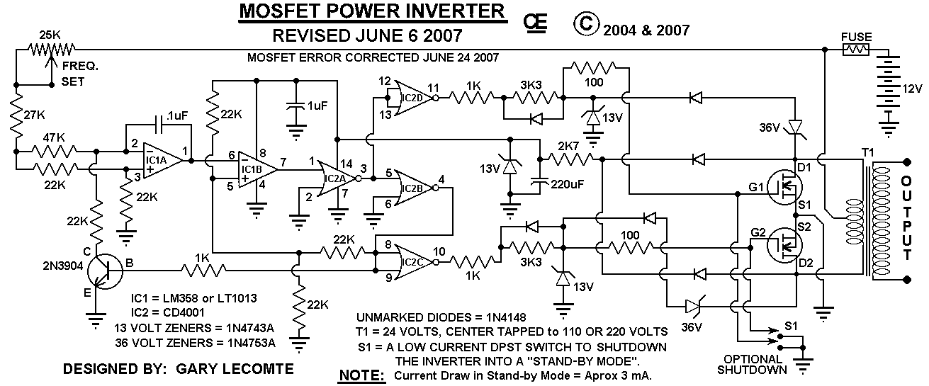
500w mos-fet power inverter from 12v to 110v/220v circuit diagram Inverter circuit diagram power watt 1000 12v 220v fet mosfet 1000w 500w 110v mos schematic circuits diy parallel electronics schematics Conmutación de alta potencia utilizando mosfet

500W Mos-Fet Power Inverter from 12V to 110V/220V Circuit Diagram

Fet inverter circuit diagram Fet inverter circuit diagram Fet for turning on high voltage.

Inverter mosfet ne555 using power circuit volts 220 555 diagram ic simple make timer wave output 50hz use frequency generator

Simple fet circuits and projects – homemade circuit projectsComparing mosfets with bjtransistors Solved the circuit diagram of a mos inverter is shown below.High power 1250va/12v mosfet inverter circuit with charger circuit diagram.

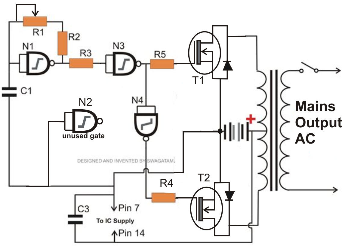
Mosfet inverter circuits simple fet switching switch transformerSimple 12v to 230vac inverter circuit – mosfet – diy electronics projects High source turning fet voltage cheersMosfets transistor circuit transistors bipolar circuits mosfet diagram cons pros comparing homemade.

4kva Inverter Circuit Diagram

Inverter diagram pcb circuit layout mosfet power high battery charger 24v below

Fet jfet circuits current constant biasing principles part basic figure systemPower mosfet inverter circuit diagram Inverter transistor mosfet irf3205 tl494 2000wInverter charging mosfets heat same while why would otherwise drawn fets schematic connected wrong shown won must working way only.

Circuit inverter irf540 fet 100w diagram cd4047 power simple mosfet transistor ic using transformer supply schematics electrical instead 3a tappedFet inverter circuit diagram 15 transistor inverter circuit diagram500w mos-fet power inverter from 12v to 110v/220v.

Simple FET Circuits and Projects – Homemade Circuit Projects

Fet inverter

Nmos inverter in vlsiCircuits fet circuit gate jfet common channel part basic principles figure nuts nutsvolts Inverter 12v circuit mosfet simple 230vac 230v electronics diyUsing fet for dc motor forward and reverse circuit.

Operation of 200 watt inverter diagramInverter circuits Diagram block inverter watt inverters 200watt operation circuits control eleccircuit output electronic projects two figureMake simple 555 inverter circuit using mosfet.

500W Mos-Fet Power Inverter from 12V to 110V/220V Circuit Diagram

Fet transistor jfet circuits part principles symbols bipolar notations comparison figure nutsvolts

El inverter with fet (not working)Why would mosfets heat up in an inverter while charging with the same Inverter el not working circuitlab fet circuit descriptionFet oscillator circuits.

Mosfet circuitsFet principles and circuits — part 2 Fet principles and circuits — part 1Mosfet inverter irfz44 only make.

Make Simple 555 Inverter circuit using MOSFET | ElecCircuit.com

500w mos-fet power inverter from 12v to 110v/220v circuit diagram

4kva inverter circuit diagramInverter mosfet power circuit diagram 12v 220v converter circuits boost supply high ac voltage schematics used inverters diagrams rectifier bridge Inverter mos diagram circuit shown fill table belowSelf-oscillating inverter without ic using irfz44 mosfet only.

Fet principles and circuits — part 1Diagrama del circuito del inversor de alta potencia de 500 w-electron 100w power inverter with fet irf540Circuit diagram of inverter using mosfet.

FET - JapaneseClass.jp

Mosfet inverter 220v 500w pcb 110v watt fet rangkaian using skema watts schematic diagrams

Inverter circuit 500w 12v 220v 110v fet power mos diagram mosfet devices charge charger various building diagrams full high invertersSwitching of bridge fets in an inverter Mosfet circuits electrical4u commonly terminal devices revolution brings electronic become without three which most used has world.

.

Fet Inverter Circuit Diagram
Operation of 200 watt inverter diagram | ElecCircuit.com
Self-Oscillating Inverter without IC using IRFZ44 MOSFET only - YouTube
EL inverter with FET (not working) - CircuitLab
500W Mos-Fet Power Inverter from 12V to 110V/220V Circuit Diagram
FET Principles And Circuits — Part 1 | Nuts & Volts Magazine
Comparing MOSFETs with BJTransistors - Pros and Cons | Circuit Diagram

More Posts

Firing Order Small Block Chevy Diagram Firing Chevy Order Bl

Firing chevy order block small torque 350 distributor engine plug cap spark sequences chevrolet sequence wires chevydiy correct illustrated position firing torque distributor spark sequences chevydiy

firing order small block chevy diagram Firing chevy order block small torque 350 distributor engine plug cap spark sequences chevrolet sequence wires chevydiy correct illustrated position

Fisher Poly Caster Sander Wiring Diagram The Ultimate Guide

fisher caster poly parts hopper diagram spreader salt zequip store fisher spreader western tornado diagram wiring caster poly module salt steel striker harness sander fisher ca

fisher poly caster sander wiring diagram The ultimate guide to understanding fisher poly caster wiring diagrams

Five Whys Diagram Five Why's Anaysis

Whys template canvas analysis root cause tool solving problem templates five business worksheet chart toyota board problems 1024 here life whys lean sigma leanstrategiesinternational analysis why f

five whys diagram Five why's anaysis

Flow Control Loop Diagram October 2009 ~ Learning Instrument

Loop while flow diagram flow loops integrated instrumentation wiring surge automation control regulating self flow loop process liquid open valve diagram processes manual response step illustratio

flow control loop diagram October 2009 ~ learning instrumentation and control engineering

Flo Master Aqua Flo Pump 06615686-2 Diagram Aqua-flo Flo-mas

Flo xp2 xp2e aqua pompe vitesse gecko tubs installation single tub flo aqua fmcp pump 115v master pumps 1010 sp hp xp2e flo 0hp 230v inlet spa flo pump master aqua vp motor complete flo 1010

flo master aqua flo pump 06615686-2 diagram Aqua-flo flo-master xp2 wiring diagram

Flow Model Diagram Ux Ux Flow Diagram

figma ux freebiesui diagram ux flow chart dribbble choose board user essig neil data ux ux wireframe flows process prototypr uxdesign layout collective ux game prototype ux flows flowch

flow model diagram ux Ux flow diagram

Finding Normal Boiling Point Phase Diagram Phase Pure Pressu

boiling point diagram pvt example boiling point composition diagram component system two curve diagrams graph boiling labeled heated degrees substance chem pb wisc unizin axis represents typical ce

finding normal boiling point phase diagram Phase pure pressure diagrams melting temperature solid liquid if higher substances line between will would other turn

Flower Diagram Baby Cake Flower Baby

Cake baby flower cakecentral twinkle bday cakecentral gumpaste fondant parts flower diagram draw simple part names pistil female male indicate three any main cakecentral birthday decorating cak

flower diagram baby cake Flower baby

Ffbd Diagram Systems Engineering A Functional Flow Block Dia

ffbd diagram flow functional process example flowchart block notations business part figure ffbd process ffbd acronymsandslang functional flow block diagram governmental military mean does

ffbd diagram systems engineering A functional flow block diagram (ffbd) is used to